
By Saad Iqbal
The liquid dump valve on a three-phase separator sticks closed. Nobody notices for ninety seconds — the pump feeding the vessel doesn’t know or care that the outlet is blocked, so it keeps pushing produced water in at full rate. Level climbs, then pressure climbs, and the only thing standing between a routine upset and a vessel failure is a pressure safety valve (PSV) sized to pass that flow before the shell sees a pressure it was never built for.
Getting pressure relief valve sizing right is one of those calculations every production and facilities engineer eventually has to run, and API 520 Part I gives you the method. This tutorial walks through the liquid-service case start to finish: define the scenario, pick the correction factors, run the equation, round up to a real orifice, and automate it so you never do it by hand again.
Prerequisites
- Required relief rate, Q — the worst-case liquid flow the valve must pass (gpm). Here: 100 gpm, from a blocked-outlet / pump-deadhead scenario.
- Set pressure — 150 psig, with 10% allowable overpressure (standard for a single valve on liquid service).
- Backpressure — 15 psig in the vent/relief header.
- Specific gravity, G — 1.00 (produced water) at relieving temperature.
- Valve configuration — conventional spring-loaded PSV, no rupture disc upstream.
- A copy of API RP 520 Part I (sizing) and API RP 526 (standard orifice areas) for reference — optional but useful.

Step 1 — Define the Relieving Scenario
Every relief valve calculation starts with a scenario, not a formula. Here it’s a blocked outlet: the liquid dump valve on the separator closes (or plugs) while the inlet pump keeps running. Nothing downstream can take the flow, so the full inflow rate becomes the required relief rate once the vessel reaches set pressure. Other common liquid scenarios — control valve fail-closed, thermal expansion in a blocked-in line, tube rupture in an exchanger — all reduce to the same question: what’s the maximum liquid flow this valve has to pass, and at what pressure?
For this job: Q = 100 gpm (the pump’s rated capacity, since nothing else limits the inflow once the outlet is blocked).

Step 2 — Choose the Valve Type and Backpressure Correction, Kw
Backpressure in the downstream relief header reduces how much a spring-loaded valve can pass, and how much correction you need depends on the valve type:
- Conventional valve: the spool directly communicates with the header. Fine as long as built-up backpressure stays under roughly 10% of set pressure — beyond that the valve can chatter or the set point drifts, so Kw = 1.0 only holds in that low-backpressure band.
- Balanced bellows valve: a bellows isolates the spring from backpressure, so the valve tolerates much higher backpressure — but capacity derates smoothly as backpressure rises, which is what Kw captures.
Our vent header runs at 15 psig against a 150 psig set pressure — about 10% — right at the edge of what a conventional valve tolerates cleanly. We’ll use a conventional valve here: Kw = 1.0.

Step 3 — Pick Kd, Kc, and Kv
Three more factors round out the equation. None of them need a model — API 520 gives you defensible preliminary values directly:
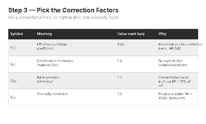
Kd (effective discharge coefficient) is 0.65 for a preliminary, orifice-selection-stage calculation on a conventional or pilot-operated valve — use the manufacturer’s certified Kd once you’ve picked an actual valve. Kc is 1.0 whenever there’s no rupture disc upstream of the valve (0.9 if there is one). Kv, the viscosity correction, is 1.0 for any liquid turbulent enough that Reynolds number clears about 4,000 at the orifice — true for produced water, true for most hydrocarbon liquids outside of cold, viscous crudes.
Step 4 — Pressure Relief Valve Sizing: the API 520 Liquid Equation
With every input in hand, the API 520 liquid orifice area equation is:
A = Q / (38 × Kd × Kw × Kc × Kv) × √(G / ΔP)- A = required effective orifice area, in²
- Q = required relief rate, gpm
- Kd, Kw, Kc, Kv = correction factors from Steps 2–3
- G = specific gravity of the liquid at relieving temperature
- ΔP = P1 − P2, psi (P1 = relieving pressure = set pressure × 1.10 overpressure; P2 = total backpressure)

Plugging in our numbers: P1 = 150 × 1.10 = 165 psig, P2 = 15 psig, so ΔP = 150 psi. With Kd·Kw·Kc·Kv = 0.65 × 1.0 × 1.0 × 1.0 = 0.65:
A = 100 / (38 × 0.65) × √(1.00 / 150)
A = 4.049 × 0.0816
A = 0.33 in²
Step 5 — Round Up to a Standard API 526 Orifice
You never order a valve with a bespoke 0.33 in² orifice — API 526 standardizes relief valve orifice sizes into lettered designations (D through T), each with a fixed effective area. You pick the smallest standard orifice whose area is at or above your calculated requirement.

Orifice F (0.307 in²) is just short of our 0.33 in² requirement, so we round up to orifice G (0.503 in²). That’s the designation you take to the valve manufacturer’s catalog to pick an actual PSV.
Automate It With Python
Once you’ve sized one valve by hand and trust the method, there’s no reason to repeat the arithmetic for the next twenty. This function takes the same inputs and returns both the required area and the selected standard orifice:
# Requires: Python 3 (https://www.python.org)
API_526_ORIFICES = {
    "D": 0.110, "E": 0.196, "F": 0.307, "G": 0.503,
    "H": 0.785, "J": 1.287, "K": 1.838, "L": 2.853,
    "M": 3.60,  "N": 4.34,  "P": 6.38,  "Q": 11.05,
    "R": 16.0,  "T": 26.0,
}

def liquid_psv_area(Q_gpm, G, set_psig, overpressure, backpressure_psig,
                     Kd=0.65, Kw=1.0, Kc=1.0, Kv=1.0):
    """API 520 Part I liquid-service orifice area, in square inches."""
    P1 = set_psig * (1 + overpressure)
    dP = P1 - backpressure_psig
    A = Q_gpm / (38 * Kd * Kw * Kc * Kv) * (G / dP) ** 0.5
    return A

def select_orifice(area_required):
    """Smallest standard API 526 orifice at or above the required area."""
    for letter, area in sorted(API_526_ORIFICES.items(), key=lambda kv: kv[1]):
        if area >= area_required:
            return letter, area
    raise ValueError("Required area exceeds the largest standard orifice (T).")

area = liquid_psv_area(Q_gpm=100, G=1.00, set_psig=150,
                        overpressure=0.10, backpressure_psig=15)
letter, orifice_area = select_orifice(area)
print(f"Required area: {area:.3f} in^2")
print(f"Selected orifice: {letter} ({orifice_area} in^2)")
# Required area: 0.331 in^2
# Selected orifice: G (0.503 in^2)
Drop that into a sizing spreadsheet or a ChatGPT– or Claude-assisted workflow and you can run every relief case on a facility in minutes instead of an afternoon with a calculator and a copy of API 520.
Expected Result and How to Verify It
You should land on a required area of about 0.33 in², rounding up to API 526 orifice G (0.503 in²). To sanity-check the selection, run the equation backwards: plug the selected orifice’s area back in and solve for the flow it can actually pass at your relieving pressure.
Q_capacity = 0.503 * 38 * 0.65 * (150 / 1.00) ** 0.5
# Q_capacity ≈ 152 gpm, comfortably above the 100 gpm requirement
If the rated capacity of your selected orifice doesn’t clear the required relief rate with margin, you’ve either made an arithmetic error or need to go up a size — don’t round down to save money on the valve.
Common Pitfalls
- Using the gas/vapor equation for a liquid case. The two API 520 sizing equations are not interchangeable — mixing them up gives you an area that’s wrong by a large factor, not a small one.
- Forgetting the conventional-valve backpressure limit. If built-up backpressure creeps above roughly 10% of set pressure, a conventional valve can open erratically; that’s when you need a balanced bellows design and a real Kw correction, not Kw = 1.0.
- Treating Kd = 0.65 as final. It’s a preliminary, orifice-selection value. Once you’ve picked an actual valve model, use the manufacturer’s ASME-certified Kd for the final capacity check.
- Mixing gauge and absolute pressure. ΔP = P1 − P2 works fine in gauge pressure as long as both P1 and P2 are in the same units — don’t convert just one of them to psia.
Relief valve sizing sits right next to two other calculations worth having in your back pocket: Vertical Two-Phase Separator Sizing (the vessel this PSV is probably protecting), and How to Calculate MAASP, another pressure-limit check that upstream engineers run constantly. If erosion in the discharge piping downstream of a relief event is also on your mind, the API RP 14E erosional velocity check is the natural next read.
