
By Saad Iqbal
A production foreman in the Permian is standing next to a brand-new wellhead, looking at a separator vendor’s quote for a vessel twice the size he actually needs. He paid for it anyway last time, because the alternative — a separator that slugs liquid into the gas sales line during a rate upset — costs more in flared gas and pipeline penalties than the oversized steel ever will. Vertical two-phase separator sizing isn’t exotic math. It’s two competing constraints, a handful of field data, and about twenty minutes of arithmetic that most engineers either do from memory with rules of thumb that are decades stale, or skip entirely and let the vendor decide. Here’s the calculation done properly, with real equations, a worked numeric example, and the Python you need so you only ever do it once by hand.
Why Undersizing (or Oversizing) a Separator Actually Costs You
A vertical separator fails in exactly two directions, and both are expensive. Size the diameter too small for the gas rate and droplets of liquid get carried out the gas outlet faster than gravity can pull them down — that’s liquid carryover, and downstream it fouls compressor suction scrubbers, trips high-level shutdowns, and shows up as unaccounted-for liquid in your gas sales measurement. Size the liquid retention volume too small and the opposite happens: gas breaks out of solution inside the liquid leg and bubbles into the oil outlet, which a pipeline buyer will reject on a BS&W or gas-in-oil spec. Oversize on purpose to be safe and you’ve bought steel, freight, and a bigger footprint than the pad needs, for a vessel that may never see the design rate. The fix is sizing both constraints independently, then picking the diameter that satisfies whichever one is more restrictive — which is exactly what vertical two-phase separator sizing means in practice.
Prerequisites
- Design gas rate (MMscfd) and liquid rate (bopd) at the operating pressure and temperature you’re sizing for — use the peak expected rate, not average.
- Operating pressure (psig) and temperature (°F) at the separator inlet.
- Gas specific gravity (relative to air) and oil API gravity, from a recent fluid analysis or allocation report.
- A gas compressibility factor (Z) for the operating condition — pull one from a Standing-Katz chart or calculate it; this tutorial assumes you already have it.
- A calculator or Python 3 with no special libraries required for the hand method, or the free fluids package if you want to automate the correlation lookups.
Worked example inputs used throughout this tutorial: gas rate 4.5 MMscfd, liquid rate 1,200 bopd, operating pressure 250 psig (264.7 psia), operating temperature 100°F (560°R), gas specific gravity 0.75, oil gravity 35°API, and Z = 0.88 at these conditions.
Step 1 — Convert Your Inputs to Fluid Densities
Every separator sizing equation runs on density, not API gravity or specific gravity directly, so the first move is converting both. Oil density in lb/ft³ comes from the standard API gravity relationship:
ρoil = [141.5 / (131.5 + °API)] × 62.4
For 35°API oil: SG = 141.5 / 166.5 = 0.850, so ρoil = 0.850 × 62.4 = 53.0 lb/ft³.
Gas density needs the real gas law in field units, because gas is compressible and oil essentially isn’t:
ρgas = (2.70 × γg × P) / (Z × T), with P in psia and T in °R.
ρgas = (2.70 × 0.75 × 264.7) / (0.88 × 560) = 536.1 / 492.8 = 1.09 lb/ft³.
Why it matters: every line of code and every correlation below is a function of the density difference between the liquid and the gas. Get the Z-factor wrong by 10% and your gas density — and therefore the whole gas-capacity calculation — is off by roughly that much, silently.

Step 2 — Find the Maximum Allowable Gas Velocity (Souders-Brown)
The Souders-Brown equation sets the fastest the gas can rise through the vessel before it starts dragging liquid droplets up with it:
vmax = K × √[(ρoil − ρgas) / ρgas]
K is an empirical droplet-settling constant that depends on pressure and whether the vessel has a mist-extraction (demister) pad. The widely used York correlation gives K = 0.35 ft/s between 15 and 40 psia, and K = 0.430 − 0.023 ln(P) from 40 to 5,500 psia, with P in psia. The open-source Python fluids package (install with pip install fluids) implements this exact correlation as K_separator_demister_York(P), so you don’t have to hardcode it by hand once you’ve checked it once.
At 264.7 psia: K = 0.430 − 0.023 × ln(264.7) = 0.430 − (0.023 × 5.578) = 0.430 − 0.128 = 0.302 ft/s.
vmax = 0.302 × √[(53.0 − 1.09) / 1.09] = 0.302 × √47.6 = 0.302 × 6.90 = 2.09 ft/s.
Why it matters: this single number is the entire physical argument for why bigger-diameter separators can handle more gas — a wider vessel gives the gas more cross-sectional area to spread through, so it can carry the same volumetric flow at a slower, droplet-safe velocity.

Step 3 — Size the Liquid Retention Volume
Gas capacity sets a minimum diameter; liquid retention sets a minimum volume, and the two pull the final vessel shape in different directions. The liquid needs enough residence time inside the vessel for entrained gas bubbles to actually separate out before the oil leaves through the liquid outlet. For a light, two-phase oil like this one, a 1-minute retention time is a standard starting point (heavier, emulsion-prone crudes need 3 minutes or more — check your own fluid before copying this number):
Vliquid (bbl) = qliquid (bopd) × tr (min) / 1,440
Vliquid = 1,200 × 1 / 1,440 = 0.833 bbl = 4.68 ft³ (1 bbl = 5.615 ft³).
That volume has to fit as a cylinder of liquid inside whatever diameter you eventually pick, so the required liquid height for a trial diameter D (ft) is hliquid = Vliquid / (π/4 × D²) — which is exactly why this step can’t be finished until you iterate diameter against both constraints together in Step 4.
Why it matters: skip this step and size on gas capacity alone, and you can end up with a vessel wide enough for the gas but too short to hold a minute of liquid — the level control will hunt constantly and gas will blow through the liquid outlet on every upset.

Step 4 — Iterate Diameter Until Both Constraints Agree
Now put gas and liquid together. First, convert the 4.5 MMscfd design gas rate from standard conditions to actual cubic feet per second at 264.7 psia and 560°R, using the real gas law with standard conditions of 14.65 psia and 520°R:
Qactual = 4,500,000 × (14.65/264.7) × (0.88 × 560/520) / 86,400 = 2.73 ft³/s.
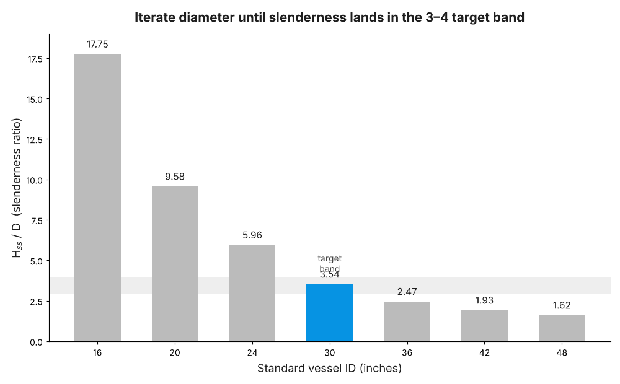
The gas-capacity-controlled minimum diameter comes from Amin = Qactual / vmax = 2.73 / 2.09 = 1.31 ft², giving Dmin = √(4A/π) = 1.29 ft (15.5 in). Then check slenderness — the ratio of seam-to-seam shell length to diameter, which standard vertical-separator practice keeps between 3 and 4 for an economical vessel that isn’t top-heavy or absurdly squat. Using a vapor-space height rule of thumb of 1×D above the liquid level:
Slenderness = [hliquid(D) + D] / D, where hliquid(D) = 4.68 / (π/4 × D²)
Trying D = 16 in (1.333 ft): hliquid = 4.68 / 1.396 = 3.35 ft. Seam-to-seam length = 3.35 + 1.33 = 4.68 ft. Slenderness = 4.68 / 1.33 = 3.51 — squarely inside the 3–4 target band, and the 16-inch diameter clears the 15.5-inch gas-capacity minimum with margin. At that diameter, actual gas velocity is 2.73 / 1.396 = 1.95 ft/s, safely under the 2.09 ft/s limit.
Why it matters: this is the step most hand calculations skip — people size for gas, forget to re-check slenderness, and either ship a diameter that’s technically big enough for gas but produces an oddly stubby or oddly tall vessel that’s expensive to fabricate or unstable to mount.
Step 5 — Automate the Vertical Two-Phase Separator Sizing Calculation in Python
Once you trust the method by hand, wrap it in a function so the next well takes thirty seconds, not twenty minutes. This reproduces every step above, including the York K-factor correlation:
import math

def size_vertical_separator(q_gas_mmscfd, q_liq_bopd, p_psig, t_f,
                             sg_gas, api_oil, z_factor, t_retention_min=1.0):
    P = p_psig + 14.65          # psia
    T = t_f + 459.67             # Rankine

    rho_oil = (141.5 / (131.5 + api_oil)) * 62.4          # lb/ft3
    rho_gas = (2.70 * sg_gas * P) / (z_factor * T)        # lb/ft3

    # York demister K-factor correlation, ft/s
    K = 0.35 if P <= 40 else 0.430 - 0.023 * math.log(P)

    v_max = K * math.sqrt((rho_oil - rho_gas) / rho_gas)  # ft/s

    q_actual = (q_gas_mmscfd * 1e6 * (14.65 / P) *
                (z_factor * T / 520) / 86400)             # ft3/s
    d_gas_min = math.sqrt(4 * (q_actual / v_max) / math.pi)  # ft

    v_liq_ft3 = (q_liq_bopd * t_retention_min / 1440) * 5.615

    def slenderness(d_ft):
        h_liq = v_liq_ft3 / (math.pi / 4 * d_ft ** 2)
        return (h_liq + d_ft) / d_ft

    d_trial = d_gas_min
    while slenderness(d_trial) > 4.0:
        d_trial += 0.01

    return {
        "rho_oil_lb_ft3": round(rho_oil, 2),
        "rho_gas_lb_ft3": round(rho_gas, 3),
        "K_ft_s": round(K, 3),
        "v_max_ft_s": round(v_max, 2),
        "d_gas_min_in": round(d_gas_min * 12, 1),
        "d_selected_in": round(d_trial * 12, 1),
        "slenderness": round(slenderness(d_trial), 2),
    }

result = size_vertical_separator(4.5, 1200, 250, 100, 0.75, 35, 0.88)
print(result)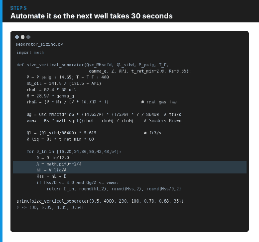
If you’re pasting raw field data from a spreadsheet instead of typing numbers by hand, an AI coding assistant like Claude or ChatGPT can turn this function into a quick Excel-callable version or a batch script that sizes an entire pad’s wells in one pass — just have it verify every formula against this tutorial line by line before you trust the output on a real design.
Expected Result, Sanity Check, and Pitfalls
For this worked example you should land on a 16-inch ID vertical two-phase separator, roughly 5 feet seam-to-seam, with about 7% gas-velocity margin and a slenderness ratio of 3.5–3.75. Sanity-check any result against two things: the actual gas velocity must stay below vmax, and the final slenderness ratio must land between 3 and 4 — if either check fails, your diameter is wrong, not the vessel.
- Using standard gas rate directly as actual velocity. Scf/day is not ft³/s at operating conditions — skip the real-gas-law conversion in Step 4 and you’ll undersize badly, often by a factor of ten or more.
- Reusing a 1-minute retention time for the wrong fluid. That number assumes light, easily de-gassing oil. Heavier, foaming, or emulsion-tendency crude needs 3 minutes or more, which changes the liquid-controlled diameter substantially.
- Checking only the governing constraint. Gas capacity and liquid retention both have to pass at the same diameter — verify both, every time, even when one obviously looks like it will dominate.
This sizing procedure feeds directly into downstream facilities work: once gas leaves the separator, gas gathering line sizing with the Weymouth equation picks up where this tutorial ends, and if your inlet stream arrives as true multiphase flow rather than already-separated gas and liquid, the Beggs and Brill correlation tutorial covers the upstream flowline pressure drop that sets your separator’s actual inlet conditions.
