
By Saad Iqbal
Somewhere around 02:00 on a night shift, a driller calls down that the string just “went light” and the standpipe pressure jumped. Nobody panics yet, because this is usually just a connection. But three joints later, the torque trace goes jagged and a tool joint lets go downhole. The post-job review finds the obvious cause: the drill collars were too short for the weight on bit the crew was actually running, and the neutral point had crept up into the heavy-weight drill pipe, where the connections were never designed to see cyclic compression. That failure is entirely preventable with one calculation most engineers learn once in school and then never actually run in the field. This is that calculation, done properly, with real numbers.
What the Neutral Point Actually Is
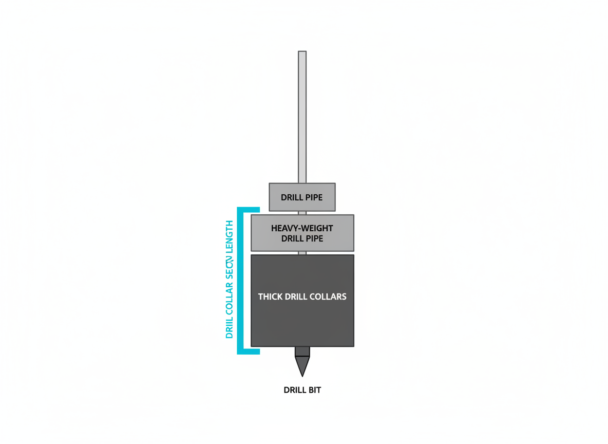
Every drillstring is in tension somewhere and compression somewhere else. Weight on bit (WOB) is created by letting part of the bottom hole assembly (BHA) hang on the bit instead of the hook — that lower section is in compression. Above it, the string is still carrying its own hanging weight, so it stays in tension. Between the two is the neutral point: the depth at which axial stress passes through zero on its way from compression to tension.
The reason this matters is buckling and fatigue, not just stress sign. Drill pipe and heavy-weight drill pipe (HWDP) connections are not rated for sustained compressive cycling the way drill collars are — collars are thick-walled, stiff, and deliberately placed to resist buckling in the lower assembly. If the neutral point lands inside the drill pipe or HWDP, that tubular spends every rotation flexing under compression, which is exactly the loading pattern that causes washouts and twist-offs at the box of a tool joint. Keeping the neutral point safely inside the drill collars, with margin, is the entire point of BHA design for weight transfer.

Prerequisites
- BHA component list with outside diameter (OD), inside diameter (ID) and length for each joint — bit, drill collars, HWDP, drill pipe
- Mud weight in pounds per gallon (ppg)
- Target weight on bit for the bit and formation you’re drilling
- A calculator, spreadsheet, or Python (we’ll automate the last step)
Worked example values used throughout this tutorial: 6-3/4″ OD x 2-13/16″ ID drill collars, 270 ft installed (nine 30 ft joints), 10 ppg mud, target WOB of 20,000 lb.
Step 1: Gather the BHA Input Data
Pull the OD, ID and length of every component from the bit up through the drill pipe, and confirm the mud weight that will actually be in the hole when WOB is applied — buoyancy depends on it. For this example: 6-3/4″ OD x 2-13/16″ ID drill collars (270 ft), 180 ft of HWDP, then drill pipe above that, circulating 10 ppg mud.
First, get the collar’s air weight per foot from its steel cross-section:
Area = (π/4) × (OD² − ID²), then weight/ft = Area × 12 × 0.2836 lb/in³ (0.2836 lb/in³ is the density of steel).
Area = (π/4) × (6.75² − 2.8125²) = 29.57 in². Weight/ft (air) = 29.57 × 12 × 0.2836 = 100.6 lb/ft — right in line with the ~100 lb/ft tabulated for this collar size in standard drill collar handbooks, which is a good sanity check before you go any further.
Step 2: Convert to Buoyed Weight with the Buoyancy Factor
Steel in air weighs more than steel hanging in mud, because the mud exerts an upward buoyant force. The standard oilfield buoyancy factor (BF) uses 65.5 ppg as the equivalent density of steel:
BF = 1 − (mud weight, ppg) / 65.5
At 10 ppg: BF = 1 − 10/65.5 = 0.8473. Every pound of steel in the hole effectively weighs 84.73% of its air weight once it’s buoyed by 10 ppg mud. This single factor is why “pick up weight” on the drill floor is always less than a tubular’s catalog weight.

Step 3: Check the Buoyed Weight Against Your Target WOB
Before solving for the neutral point, confirm the installed drill collars can actually deliver the WOB you want. Multiply the collar length by weight per foot, then by BF:
Air weight of 270 ft of collars = 270 × 100.6 = 27,162 lb. Buoyed weight = 27,162 × 0.8473 = 23,017 lb.
With a 20,000 lb target WOB, the 270 ft string has 23,017 lb of buoyed weight available — comfortably more than needed, with headroom for the safety margin in Step 5. If the buoyed weight were less than the target WOB, no amount of neutral-point math would help: you’d need more or heavier collars before going further.

Step 4: Solve for the Neutral Point
The neutral point distance from the bit, Da, is simply the target WOB divided by the buoyed weight per foot of the drill collars:
Da = WOB / (weight/ft (air) × BF)
Da = 20,000 / (100.6 × 0.8473) = 20,000 / 85.24 = 234.6 ft above the bit.
That number only means something in context: the installed collar string is 270 ft long, so the neutral point sits 234.6 ft up from the bit — comfortably inside the collars, 35.4 ft below the crossover into the HWDP.

Step 5: Apply a Safety Margin, Then Automate It
Field practice never runs the neutral point right at the top of the collars — connections there would still see occasional compression from drag, vibration and WOB overshoot. The standard rule of thumb is to keep installed drill collar length at least 1.15–1.20 times Da, which both caps the margin for WOB fluctuation and keeps the crossover connection solidly in the tension zone.
1.15 × 234.6 ft = 269.8 ft ≈ 270 ft — which is exactly the nine-joint collar string in this example. That is not a coincidence; it’s how the collar count should be chosen in the first place: solve for Da at your maximum planned WOB, apply the 15–20% margin, then round up to a whole number of joints.
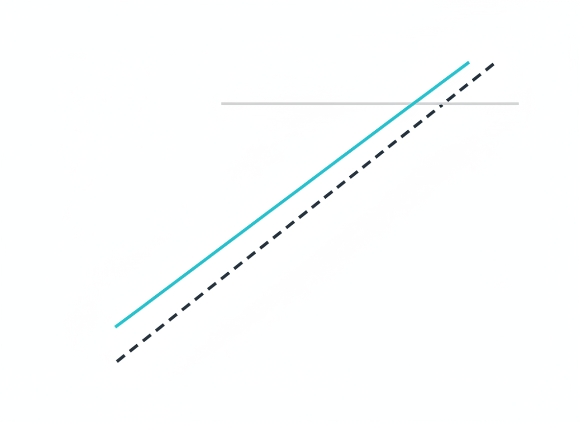
Mud weight changes every time you displace, and WOB changes every time you drill a different formation, so this isn’t a calculation to run once and forget. Here’s a short Python script that automates it — point it at your own BHA and it will plot the neutral point against WOB for any mud weight:
import numpy as np
import matplotlib.pyplot as plt

def buoyancy_factor(mud_weight_ppg):
    return 1 - mud_weight_ppg / 65.5

def collar_weight_per_ft(od_in, id_in, steel_density=0.2836):
    area_in2 = np.pi / 4 * (od_in**2 - id_in**2)
    return area_in2 * 12 * steel_density  # lb/ft, air weight

def neutral_point(wob_lb, w_air_lbft, mud_weight_ppg):
    bf = buoyancy_factor(mud_weight_ppg)
    return wob_lb / (w_air_lbft * bf), bf

# Example BHA: 6-3/4" OD x 2-13/16" ID drill collars
w_air = collar_weight_per_ft(6.75, 2.8125)
installed_length_ft = 270.0

wob_range = np.linspace(5_000, 35_000, 100)
for mud_weight in (10.0, 14.0):
    da_values = [neutral_point(w, w_air, mud_weight)[0] for w in wob_range]
    plt.plot(wob_range, da_values, label=f"{mud_weight:.0f} ppg mud")

plt.axhline(installed_length_ft, linestyle=":", label="270 ft installed")
plt.xlabel("Weight on bit (lb)")
plt.ylabel("Neutral point distance from bit, Da (ft)")
plt.legend()
plt.title("Neutral Point Sensitivity")
plt.show()

da, bf = neutral_point(20_000, w_air, 10.0)
print(f"w_air = {w_air:.1f} lb/ft, BF = {bf:.4f}, Da = {da:.1f} ft")
# w_air = 100.6 lb/ft, BF = 0.8473, Da = 234.6 ft
Run that at the start of every well program with your actual collar sizes, and again whenever mud weight or planned WOB changes materially. For teams that want pre-built petroleum engineering functions instead of hand-rolled ones, petropt packages drilling, hydraulics and PVT routines on top of Python — worth a look once you’ve confirmed the mechanics above by hand. A notebook in Jupyter is the easiest way to keep this calculation next to your well plan and re-run it in seconds as parameters change.
Verify the Result
Two quick sanity checks before you trust the number on a rig:
- Buoyed weight of the full collar string must exceed target WOB with margin — here, 23,017 lb buoyed weight comfortably clears the 20,000 lb target.
- Da must land inside the collar length with room to spare. 234.6 ft inside a 270 ft string leaves a 35.4 ft (13%) margin at the crossover, consistent with the 1.15–1.20 rule.
Common Pitfalls
- Forgetting buoyancy entirely. Using air weight instead of buoyed weight overstates available WOB by 15–20% in typical muds — exactly the margin you need for safety.
- Ignoring HWDP in the stack. HWDP has thicker walls than drill pipe and can carry some compression, but it is not rated like a drill collar; don’t plan on the neutral point sitting inside it.
- Static mud weight assumptions. A heavier kill-weight slug or a lighter displacement fluid changes BF and shifts Da — re-run the check after any significant mud weight change.
- No margin at all. Running collars sized exactly to Da with zero buffer invites exactly the cyclic-compression failure this calculation exists to prevent.
Once the neutral point is confirmed, the next things worth checking on the same BHA are torque and drag along the string and, if you’re running high-angle collars near rated burst, a casing burst pressure check. If the well path itself is still being finalized, the minimum curvature method tutorial covers the survey calculations that feed into all of these.
