
By Saad Iqbal
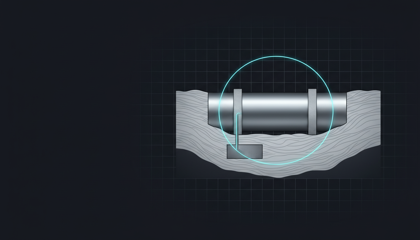
A 12-inch gathering line outside a Permian battery had been losing cathodic protection for four months before anyone noticed. The rectifier feeding its impressed-current anode bed had tripped on a blown fuse back in June. Nobody caught it, because the quarterly rectifier read wasn’t due until September, and the test-station readings a field tech did take in between were from a different, still-protected segment half a mile down the line. By the time a hydrotest flagged a wall-loss anomaly near a road crossing, the pipe had spent a full season as exactly what cathodic protection exists to prevent: the anode in its own corrosion cell. The fix was a dig-up and a sleeve repair. The rectifier fuse would have cost about four dollars.
What Cathodic Protection Is Actually Doing
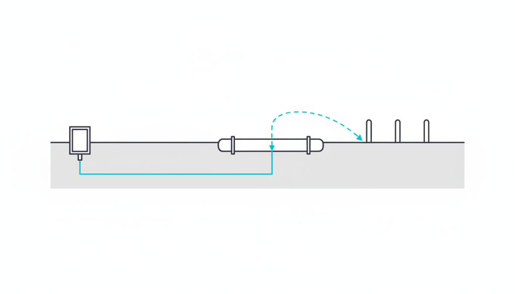
Steel buried in soil or seawater corrodes because it’s an imperfect material sitting in an electrolyte, with microscopic anodic and cathodic sites scattered across its surface, each one a tiny battery discharging metal into the ground. Cathodic protection doesn’t stop that chemistry — it overpowers it. Force enough direct current onto the structure from an external source, and the whole pipe becomes the cathode of the circuit instead of a patchwork of anodes and cathodes fighting each other. The corrosion current has to go somewhere, so it’s redirected onto a sacrificial anode (a block of zinc or magnesium that corrodes instead) or, on anything bigger than a short pipeline segment, onto an impressed-current system: a rectifier converting AC power to DC, pushing current out through a buried anode bed and back through the pipeline itself.
That’s the whole mechanism — one circuit, one rectifier, one anode bed, often protecting miles of pipe. It’s also why a single point of failure, a blown fuse, a disconnected anode lead, a collapsed anode bed, can silently take an entire segment off protection while the pipe keeps flowing and nothing on the surface looks wrong.
The Bar You’re Actually Held To
Whether a pipeline is adequately protected isn’t a judgment call — it’s measured against criteria the industry has used for decades, most of them codified in what engineers still call NACE SP0169 (now jointly stewarded by AMPP). The one every field tech learns first is the polarized potential criterion: a pipe-to-soil potential of at least −850 mV measured against a copper-copper sulfate reference electrode, with the IR drop removed from the reading. Where that’s impractical to confirm, the alternative is the 100 mV polarization criterion — showing at least 100 mV of cathodic polarization develops and decays on the structure. Neither number is arbitrary; both come from the electrochemistry of steel in near-neutral soils, where more negative potentials than roughly −850 mV reliably put the corrosion rate low enough to be considered controlled.
For regulated gas pipelines in the US, 49 CFR Part 192 turns those criteria into a schedule: cathodic protection on a buried or submerged steel pipeline has to be checked at least once each calendar year, with no more than 15 months between checks, and rectifiers get inspected roughly six times a year under typical compliance programs. That interval was reasonable when a rectifier check meant driving to it with a voltmeter. It leaves a lot of room for a four-dollar fuse to go unnoticed for most of a year.
Where the Manual Survey Actually Fails
None of this is a knowledge gap in the industry — corrosion engineers know exactly what to measure. The failure is temporal. A rectifier that trips in week one of a quarter isn’t caught until the scheduled read in week twelve, and an annual close-interval survey only snapshots the line’s potential profile on the one day someone walked it. In between, three things routinely go wrong without anyone watching:
- Rectifier output drift or loss. A blown fuse, a failed diode stack, or simply a utility outage that silently de-energizes the DC supply. The structure drifts off protection at a rate that depends on soil resistivity and coating condition, sometimes in days.
- AC or DC interference. Nearby pipelines, HVDC transmission lines, rail systems or other impressed-current beds can swing a structure’s potential in ways that mimic a healthy reading on a test meter while masking real under-protection, or conversely trigger coating disbondment from excess current.
- Reference electrode and coating drift. A degrading permanent reference cell can make a well-protected structure look like it’s failing criteria, while gradual coating damage lowers current demand in a way that looks fine on a potential reading but means more bare steel is now exposed.

How Continuous Monitoring Closes the Gap
The fix the industry has converged on isn’t a new protection method — it’s turning the existing test stations and rectifiers into always-on data points instead of quarterly ones. Remote monitoring units at rectifiers and test stations report pipe-to-soil potential, rectifier output current and voltage continuously, and the monitoring layer’s job is the same pattern-recognition problem as the artificial-lift signatures covered elsewhere on this site: compare today’s reading against that specific asset’s own recent history, and flag the deviation before it becomes a code violation.
Platforms built for this, including iFactory AI’s pipeline CP optimization tool, describe the practical difference in detection speed rather than detection capability — the physics hasn’t changed, the latency has. A rectifier fault that would previously surface at the next scheduled read, weeks to months out, gets flagged within minutes of the output current actually drifting, and a gradual anode bed degradation shows up as an early trend deviation instead of a surprise failed criterion on survey day. The same remote units also help separate the three failure types in the list above from each other: a rectifier-side problem shows up as the output current itself dropping, an interference event shows up as potential swings uncorrelated with that rectifier’s own output, and reference electrode drift shows up as a step change with no corresponding change in current demand at all.
None of this replaces the annual close-interval survey or the judgment of a corrosion engineer reading a Pearson survey or a DCVG line. What it does is shrink the blind window between the moment something actually goes wrong and the moment a human finds out, from a season down to an afternoon.
A Simple Version You Can Build Today
If your rectifiers already report output current and voltage to a historian, SCADA tag, or even a CSV export from a cellular monitor, a rolling baseline is a short script, not a procurement cycle. Python and pandas handle the trend-detection logic the same way they do for the PCP monitoring case covered in this site’s artificial-lift coverage:
import pandas as pd

# df has columns: timestamp, rectifier_id, output_current_a, output_voltage_v, pipe_to_soil_mv
df = df.sort_values(['rectifier_id', 'timestamp'])

baseline_current = df.groupby('rectifier_id')['output_current_a'].transform(
    lambda s: s.rolling(30, min_periods=10).median()
)
df['current_drift_pct'] = (df['output_current_a'] - baseline_current) / baseline_current * 100

# NACE SP0169 polarized potential criterion check (CSE reference, IR-drop corrected)
df['meets_850mv_criterion'] = df['pipe_to_soil_mv'] <= -850

alerts = df[
    (df['current_drift_pct'].abs() > 20) |      # rectifier output drifted hard
    (~df['meets_850mv_criterion'])               # potential reading fails criterion outright
]
Push the alerts table into Power BI or Looker Studio for a fleet-wide rectifier health view, and wire a n8n or Zapier flow to text the corrosion team the day a rectifier’s output first drifts, instead of waiting for whichever month its scheduled read falls in. It’s not a substitute for a properly engineered remote monitoring unit with its own telemetry and interference-rejection logic, but for an operator with existing SCADA tags on its rectifiers, it turns data that’s already being collected and ignored into an early-warning system by Friday.
Where This Fits in the Broader Corrosion Picture
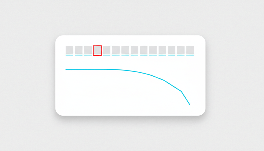
Cathodic protection monitoring is the preventive half of a corrosion program; AI corrosion rate prediction and well integrity corrosion monitoring are the half that tells you how much wall thickness is left once protection has already been imperfect for a while. A rectifier that’s been down for four months is exactly the kind of event that shows up later as an unexplained corrosion rate spike in internal UT data — the two problems are usually the same incident, caught by two different instruments at two different points in time. For a wider comparison of the sensor and software options on the market, the AI corrosion monitoring tools roundup covers where CP telemetry fits alongside UT, ER and LPR probes.
If you’re responsible for CP on buried or submerged steel today, the cheapest first move isn’t a monitoring contract — it’s pulling the last two years of rectifier reads and checking how many times a unit showed up reading zero output on a scheduled visit with no record of when it actually failed. Most CP programs find at least one. That gap is the whole argument for continuous monitoring, in one spreadsheet column.
