
By Saad Iqbal
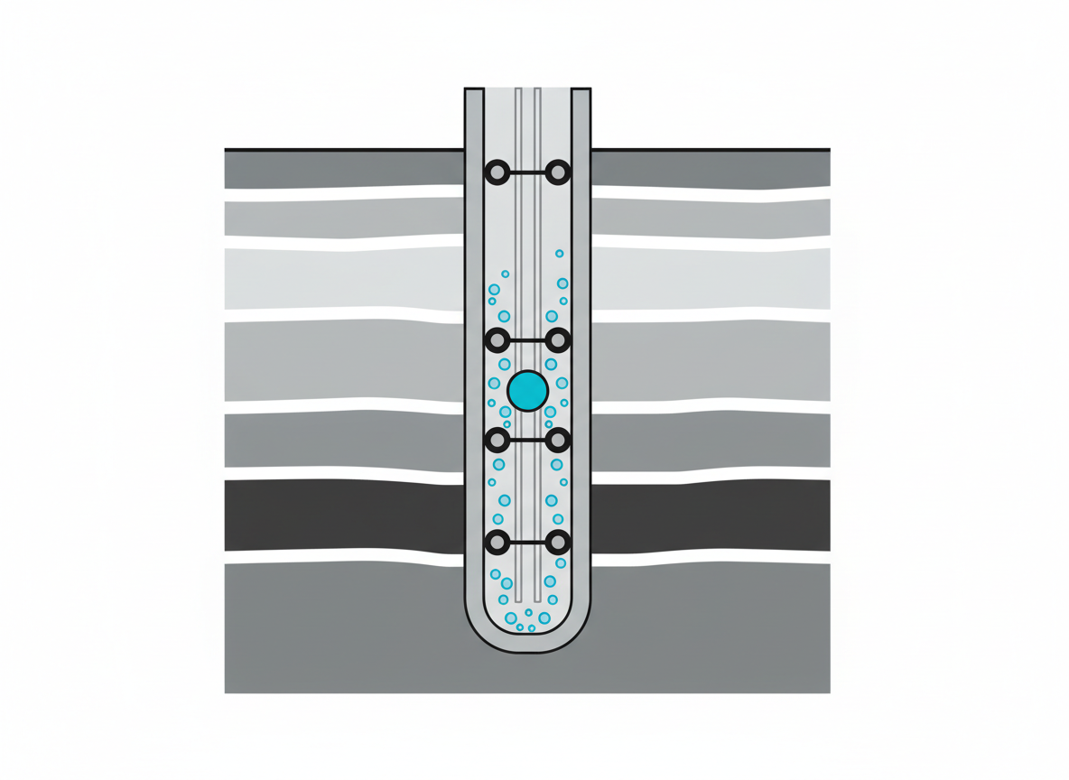
Every gas lift unloading job starts the same way: someone pulls up a hand-drawn depth-versus-pressure chart, walks two straight lines down the page with a ruler, and hopes the intersection lands where the mandrels actually are. Get the gas lift valve spacing calculation wrong and you either strand gas above a dead column of load fluid or slam a valve open too deep for the compressor to reach — both mean a rig-up to pull and re-space the string. The good news is that the whole calculation is two straight lines and a bit of algebra. Once you can do it by hand, you can hand it to Python and never draw the chart again.
Prerequisites
- Kickoff injection pressure (Pko) — the surface casing pressure your compressor can deliver to start unloading. Example: 1,200 psig.
- Minimum unloading wellhead pressure (Pwh) — the lowest tubing pressure you’re designing to at surface. Example: 100 psig.
- Load (kill) fluid gradient (Gf) — the hydrostatic gradient of the completion/kill fluid in the tubing. Example: 9.0 ppg brine → 0.468 psi/ft.
- Injection gas gradient (Gg) — the average gradient of the lift gas in the annulus at operating pressure. Example: 0.06 psi/ft for a 0.65 SG gas.
- Valve spacing safety margin (ΔPvc) — the surface pressure cushion between successive valves so the shallower valve fully closes before the next one opens. Example: 75 psi.
- A calculator or Python 3 with no special libraries (we’ll only use plain arithmetic).
What Actually Sets a Gas Lift Valve’s Depth?
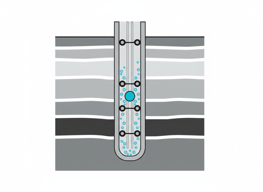
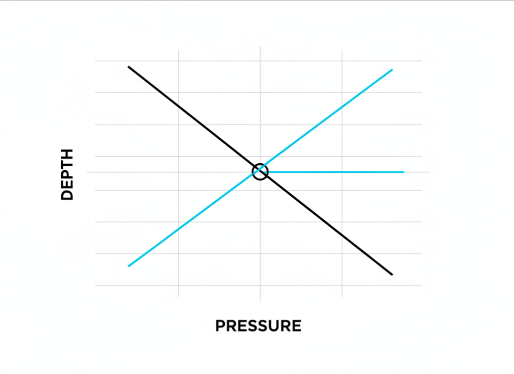
A gas lift valve opens when the pressure on its casing (gas) side exceeds the pressure on its tubing (fluid) side at that depth. During unloading, that means comparing two straight lines on a depth-vs-pressure plot:
- The injection gas line: starts at Pko at surface and increases slowly with depth at the gas gradient Gg.
- The load fluid line: starts at Pwh at surface and increases quickly with depth at the fluid gradient Gf.
Because the fluid line climbs faster than the gas line, the two lines converge as depth increases. Where they cross is the deepest point your available kickoff pressure can push gas into the tubing — the maximum depth of injection, and the natural depth for your final, operating valve.
Step 1: Find the Maximum Depth of Injection
Setting the two lines equal and solving for depth gives the single most useful number in gas lift design — the depth your compressor’s kickoff pressure can actually reach:
D_max = (P_ko − P_wh) / (G_f − G_g)Plugging in the example numbers — Pko = 1,200 psig, Pwh = 100 psig, Gf = 0.468 psi/ft, Gg = 0.06 psi/ft:
D_max = (1200 − 100) / (0.468 − 0.06)
      = 1100 / 0.408
      ≈ 2,696 ft
That’s why this step matters on its own, before you even think about the valves above it: if Dmax comes out shallower than your packer or your desired point of injection, no amount of clever spacing above it will fix the well — you need a higher kickoff pressure, a lighter kill fluid, or a different design altogether.
Step 2: Space the Unloading Valves Upward From There
Dmax is your deepest (operating) valve. The valves above it are spaced by giving each one a slightly lower effective surface pressure, using the safety margin ΔPvc as the pressure cushion between valves. Convert that pressure margin into a depth interval with the same denominator as before:
ΔD = ΔP_vc / (G_f − G_g)ΔD = 75 / 0.408 ≈ 184 ftNow step upward from Dmax by ΔD for as many valves as the well needs (five is typical for a well this depth):
| Valve | Role | Depth (ft) |
|---|---|---|
| 1 | Top / first to uncover | 1,961 |
| 2 | Unloading | 2,145 |
| 3 | Unloading | 2,328 |
| 4 | Unloading | 2,512 |
| 5 | Operating (= Dmax) | 2,696 |
This constant-pressure-differential method is the standard hand-calculation approach taught for a first-pass continuous-flow design — quick, defensible, and exactly what you want before handing the well over to full valve-performance (PPO/TRO) software for the final check.

Getting the Gas Gradient Right (Optional Refinement)
The 0.06 psi/ft used above is a flat, straight-line approximation — fine for a first-pass hand calculation, but the real injection gas gradient is not perfectly linear. It follows the static gas column equation, which accounts for gas gravity, temperature, and compressibility as the gas is compressed with depth:
P2 = P1 × exp(0.01875 × γg × D / (T̄ × Z̄))Where P1 and P2 are the pressures (psia) at surface and depth D (ft), γg is the gas specific gravity (air = 1), T̄ is the average absolute temperature in the annulus (°R = °F + 460), and Z̄ is the average gas compressibility factor. For a 0.65 SG gas, a 150°F average annulus temperature, Z̄ = 0.90, and P1 = 1,214.7 psia (1,200 psig kickoff), the pressure at 2,696 ft works out to about 1,289.6 psia — an average gradient of roughly 0.028 psi/ft, notably flatter than the 0.06 psi/ft used in the worked example. Swap in your own gas gravity, temperature, and Z-factor and the valve depths above will shift accordingly — which is exactly why this step deserves its own careful pass on any real design, not just a borrowed round number.
Step 3: Automate the Gas Lift Valve Spacing Calculation in Python
Once you trust the two formulas, there’s no reason to ever re-draw the chart. This function reproduces the worked example above and lets you re-run it instantly for a different well, kickoff pressure, or fluid gradient. Write it once in Python inside a Jupyter notebook and it becomes a permanent part of your design toolkit:
def valve_depths(Pko, Pwh, Gf, Gg, dPvc, n_valves):
    """
    Pko      : surface kickoff injection pressure (psig)
    Pwh      : desired minimum unloading wellhead/tubing pressure (psig)
    Gf       : load (kill) fluid gradient (psi/ft)
    Gg       : injection gas gradient in the annulus (psi/ft)
    dPvc     : pressure safety margin between valves (psi)
    n_valves : number of unloading valves to place, including the operating valve
    Returns valve depths in ft, shallow to deep.
    """
    d_max = (Pko - Pwh) / (Gf - Gg)
    step = dPvc / (Gf - Gg)
    depths = [d_max - i * step for i in range(n_valves)]
    return sorted(round(d) for d in depths)

depths = valve_depths(Pko=1200, Pwh=100, Gf=9.0 * 0.052, Gg=0.06, dPvc=75, n_valves=5)
print(depths)
# [1961, 2145, 2328, 2512, 2696]
Drop the numbers into a spreadsheet or a small pandas DataFrame and you have a design table you can hand straight to the completions team, with every input traceable back to the two lines you drew above.

Verify the Result
Before you trust any valve spacing calculation, sanity-check it against the two lines it came from:
- The deepest valve should equal Dmax to the foot. If it doesn’t, you’ve mixed up which gradient goes with which pressure.
- The spacing between any two adjacent valves should always equal ΔD (184 ft here) — if it drifts, check your rounding.
- Plug the shallowest valve’s depth back into the injection line: Pko + Gg × D1 should sit comfortably above Pwh + Gf × D1, confirming gas can still push fluid at that depth.
Common Pitfalls
- Using a flat gas gradient for a deep or high-pressure well. Gg = 0.06 psi/ft is a reasonable average for shallow-to-mid-depth wells; for deeper or higher-pressure strings, compute the real gas column pressure with the static gas equation instead of a straight line.
- Forgetting the safety margin entirely. Spacing valves with ΔPvc = 0 packs them too close together and they can all try to open at once during unloading.
- Treating this as the final design. This hand method sizes depths; it doesn’t size port diameters or set test-rack pressures — that still needs proper valve performance software before the string goes in the hole.
Once the depths are set, the next question is usually whether the well can actually flow at the rate you designed for — that’s exactly what nodal analysis answers, and if the well is already showing signs of instability, see how to catch gas lift instability before it becomes casing heading. For the fluid-gradient side of this calculation on a live well, the same logic underpins a kill sheet calculation.
